STM32F411CE Lab 3 – Challenge-Response System (Part 2)
Author: Shafeeque Olassery Kunnikkal | Category: Cyber Security, IoT, Penetration Testing, STM32F411 | Leave a Comment
Welcome back! In this follow-up, we continue developing the STM32F411CE Lab 3 Challenge-Response system.
Today we’ll cover:
✅ Setting up STM32CubeIDE
✅ Configuring JTAG, UART, GPIO
✅ Adding challenge-response logic
✅ Preparing for build, flash, and testing
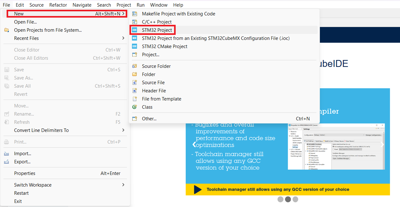
Step 1: Create the STM32CubeIDE Project
Open STM32CubeIDE → File → New → STM32 Project
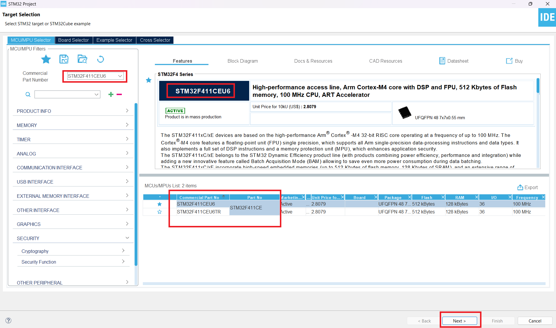
Step 2: Select the MCU
In the Target Selection window, enter:STM32F411CEU6
✅ Select the STM32F411CEU6 device and click Next.
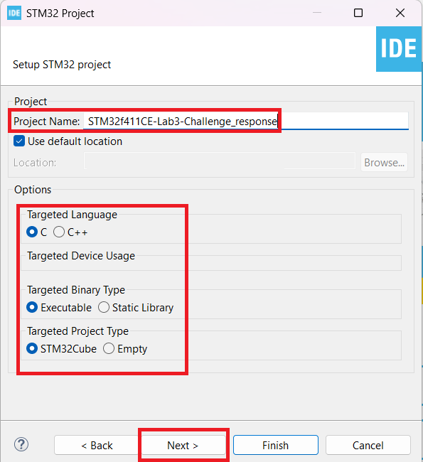
Step 3: Set Project Name and Options
- Project Name: STM32f411CE-Lab3-Challenge_response
- Language: C
- Binary type: Executable
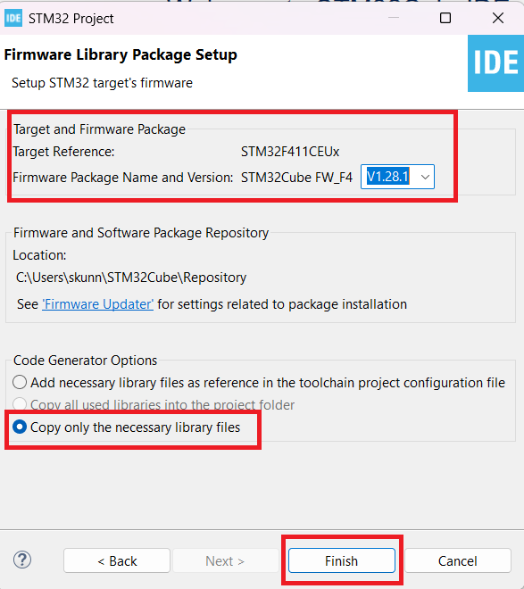
Accept the firmware package defaults and click Finish.
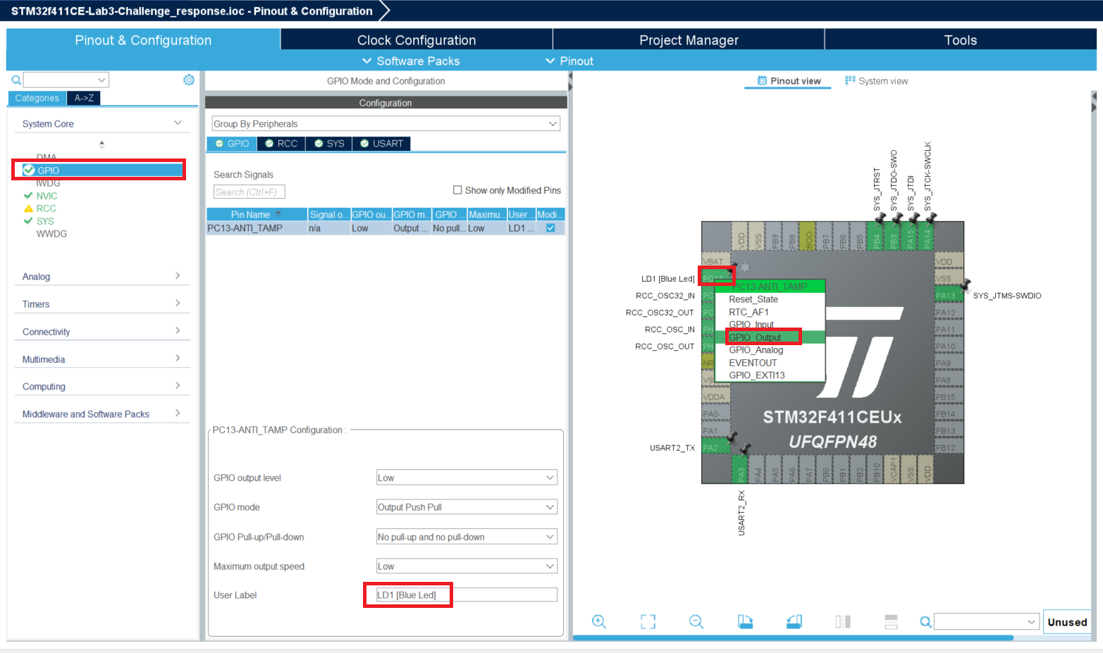
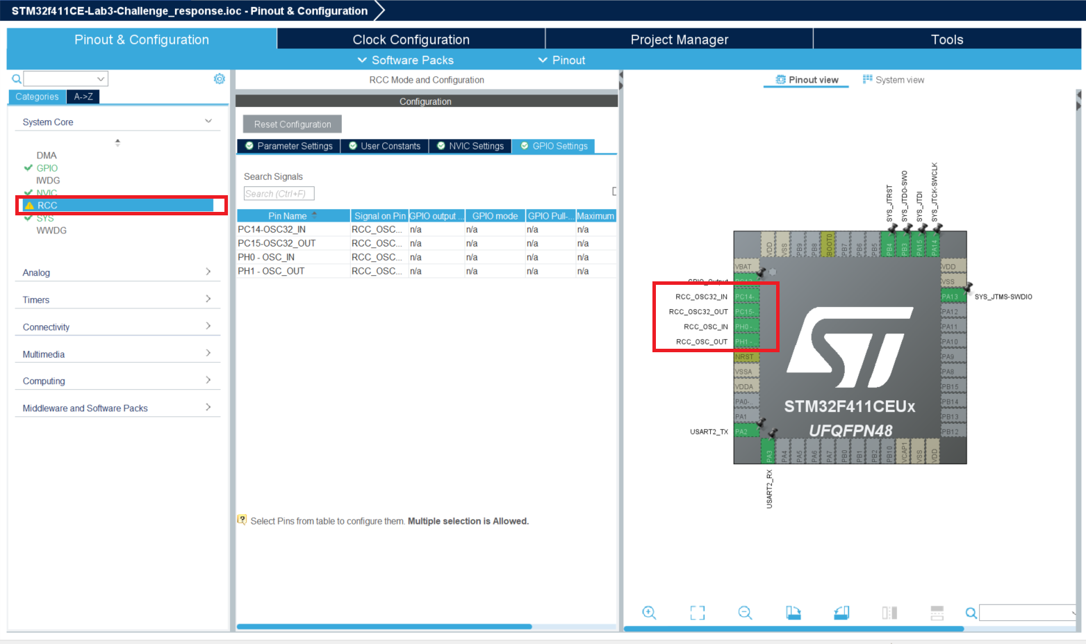
Step 4: Configure Pinout and Peripherals
In the configuration screen, set up:
- LED GPIO (PC13) → for blinking
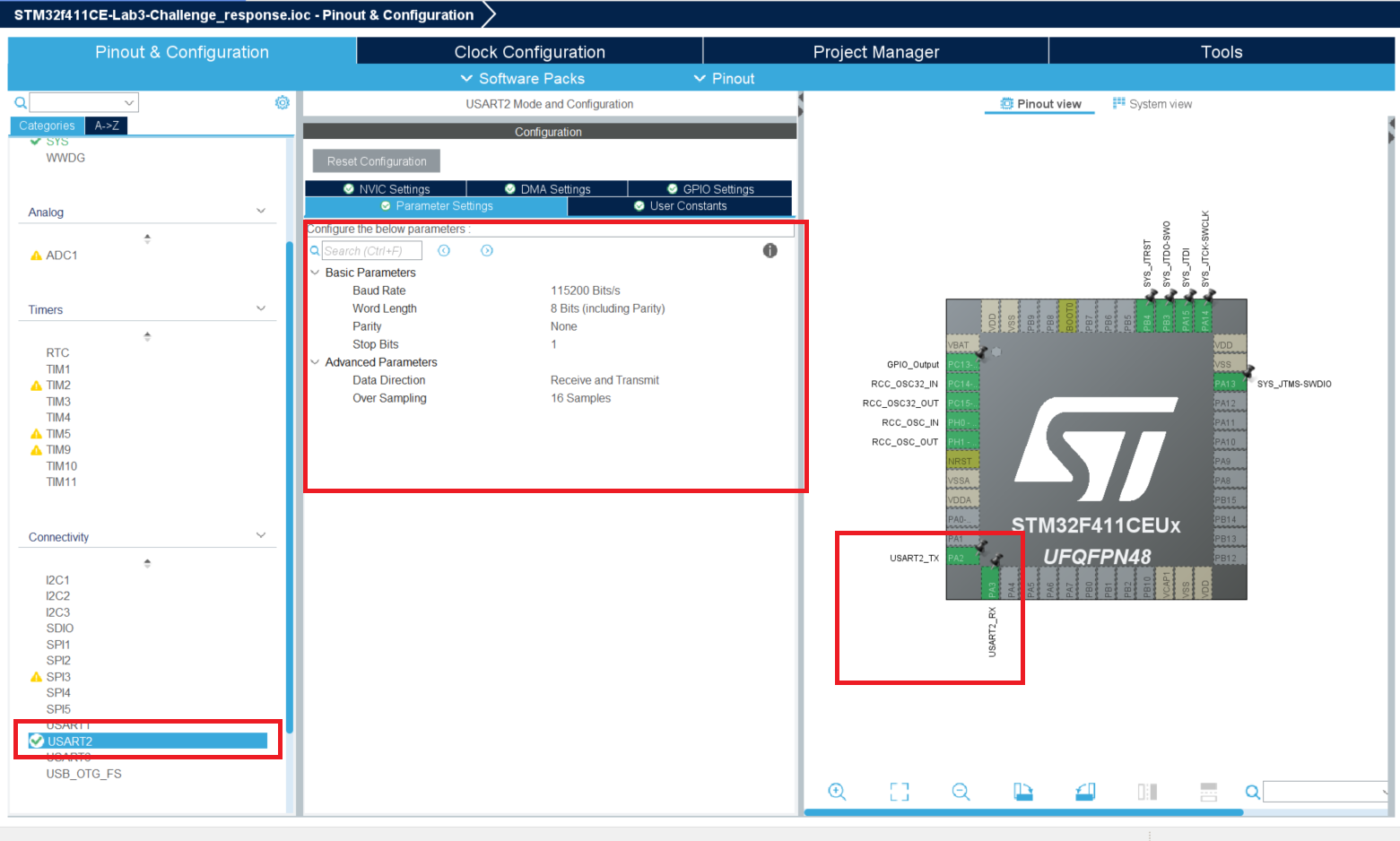
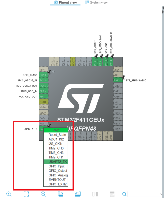
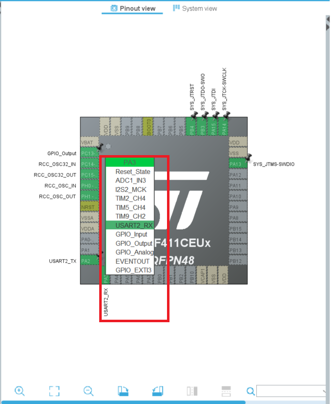
- USART2 (TX/RX) → for UART
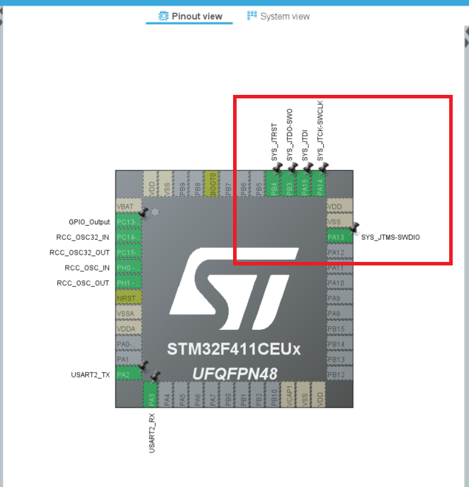
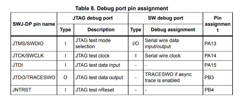
- JTAG pins → for debug
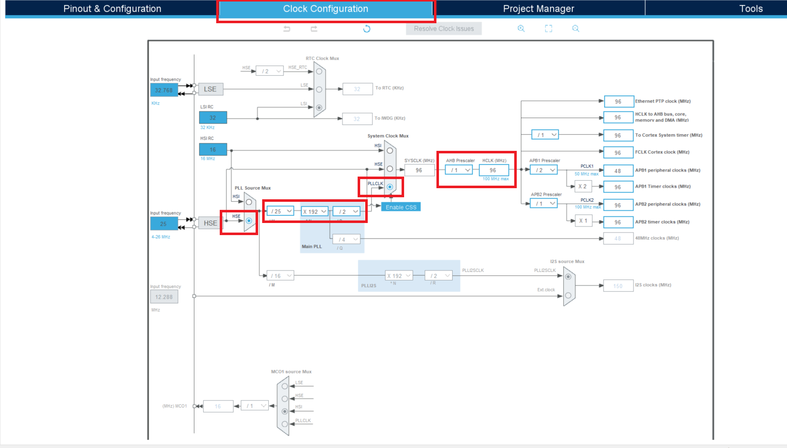
- RCC settings → adjust clocks

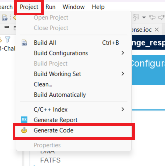
Step 5: Generate Code
Go to → Project → Generate Code. This produces the initial project structure, main application file, and HAL drivers.
Step 6: Review Generated Files
Open the generated files in your project, especially the main application file, to check the structure and ready it for customization.
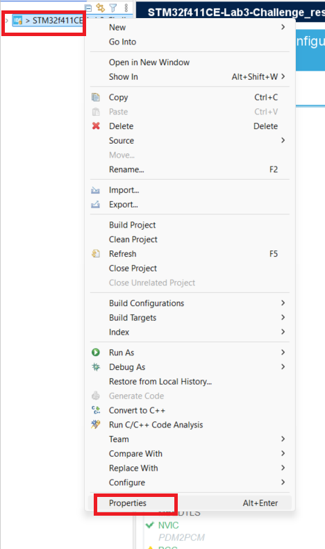
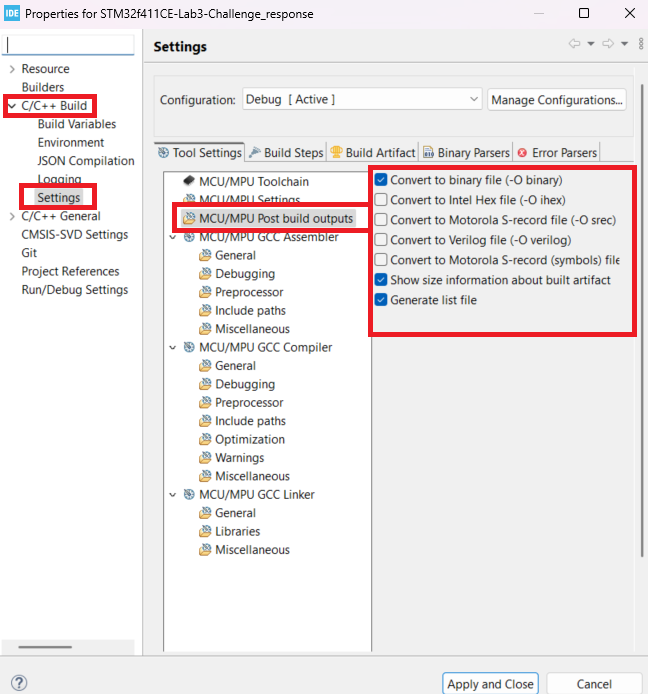
Step 7: Enable Binary Output
✅ Right-click the project → Properties → Configure output settings to also generate .bin files.
Why We Refined the LED Code
In embedded development, using blocking code (such as delays) causes the microcontroller to halt while waiting.
For example, if the LED blinking logic uses a blocking delay, the system can’t process UART input or perform other tasks.
To improve responsiveness, we implemented a non-blocking LED control module.
Instead of delays, it uses time comparisons, allowing the system to keep running while the LED blinks in the background — critical for multitasking and system responsiveness.
Why We Insert Code Only in IDE-Provided Sections
STM32CubeIDE automatically generates key project files when you click Project → Generate Code.
If you add custom code outside the provided USER CODE sections, it can be overwritten or deleted during regeneration or when opening the project in a new workspace.
To prevent this, always place your custom code inside the protected areas marked:
- USER CODE BEGIN Includes → USER CODE END Includes
- USER CODE BEGIN PV → USER CODE END PV
- USER CODE BEGIN 2 → USER CODE END 2
- USER CODE BEGIN 3 → USER CODE END 3
⚠ Double-check: When modifying IDE-generated files, ensure all changes are inside these sections.
This protects your work during future regenerations or IDE transitions.
Custom .c and .h Files We Added
challenge.h
#ifndef CHALLENGE_H
#define CHALLENGE_H

#include "stm32f4xx_hal.h"

uint32_t GenerateChallenge(void);
uint8_t ValidateResponse(uint32_t challenge, uint32_t response);

#endif
challenge.c
#include "challenge.h"
#include <stdlib.h>
#include <time.h>

#define CHALLENGE_CONSTANT 3

uint32_t GenerateChallenge(void) {
    srand(HAL_GetTick());
    return (rand() % 100) + 1;
}

uint8_t ValidateResponse(uint32_t challenge, uint32_t response) {
    return (response == challenge * CHALLENGE_CONSTANT);
}
led_control.h
#ifndef INC_LED_CONTROL_H_
#define INC_LED_CONTROL_H_

#include "stm32f4xx_hal.h"

typedef struct {
    GPIO_TypeDef *port;
    uint16_t pin;
    uint8_t count;
    uint32_t interval;
    uint32_t last_toggle;
    uint8_t is_active;
} LedBlinkController;

void LED_StartBlinking(LedBlinkController *controller, GPIO_TypeDef *port, uint16_t pin, uint8_t count);
void LED_Update(LedBlinkController *controller);

#endif
led_control.c
#include "led_control.h"

void LED_StartBlinking(LedBlinkController *controller, GPIO_TypeDef *port, uint16_t pin, uint8_t count) {
    controller->port = port;
    controller->pin = pin;
    controller->count = count * 2;
    controller->interval = 200;
    controller->last_toggle = HAL_GetTick();
    controller->is_active = 1;
}

void LED_Update(LedBlinkController *controller) {
    if (!controller->is_active) return;

    uint32_t now = HAL_GetTick();
    if (now - controller->last_toggle >= controller->interval) {
        HAL_GPIO_TogglePin(controller->port, controller->pin);
        controller->last_toggle = now;
        controller->count--;

        if (controller->count == 0) {
            controller->is_active = 0;
            HAL_GPIO_WritePin(controller->port, controller->pin, GPIO_PIN_RESET);
        }
    }
}
uart_interface.h
#ifndef INC_UART_INTERFACE_H_
#define INC_UART_INTERFACE_H_

#include "stm32f4xx_hal.h"

void UART_SendString(const char *str);
void UART_ReadString(char *buffer, uint16_t size);
void UART_ClearScreen(void);

#endif
uart_interface.c
#include "uart_interface.h"
#include <string.h>
#include <stdio.h>

extern UART_HandleTypeDef huart2;

void UART_SendString(const char *str) {
    HAL_UART_Transmit(&huart2, (uint8_t *)str, strlen(str), HAL_MAX_DELAY);
}

void UART_ReadString(char *buffer, uint16_t size) {
    uint16_t i = 0;
    char ch;
    while (i < size - 1) {
        HAL_UART_Receive(&huart2, (uint8_t *)&ch, 1, HAL_MAX_DELAY);
        if (ch == '\r' || ch == '\n') break;
        buffer[i++] = ch;
    }
    buffer[i] = '\0';
}

void UART_ClearScreen(void) {
    char clear[] = "\033[2J\033[H";
    UART_SendString(clear);
}
Modified main Application Snippets
Includes Section
/* USER CODE BEGIN Includes */
#include "challenge.h"
#include "led_control.h"
#include "uart_interface.h"
#include <string.h>
#include <stdio.h>
#include <stdlib.h>
/* USER CODE END Includes */
Private Typedef Section
/* USER CODE BEGIN PTD */
LedBlinkController ledController;
/* USER CODE END PTD */
Private Variables Section
/* USER CODE BEGIN PV */
uint8_t challengeCount = 0;
/* USER CODE END PV */
Initialization Section
/* USER CODE BEGIN 2 */
UART_SendString("Booting up... Blinking LED.\r\n");
LED_StartBlinking(&ledController, LD1_GPIO_Port, LD1_Pin, 5);

while (ledController.is_active) {
    LED_Update(&ledController);
}
/* USER CODE END 2 */
Main Loop Section – inside While(1)
/* USER CODE BEGIN 3 */
HAL_GPIO_WritePin(LD1_GPIO_Port, LD1_Pin, GPIO_PIN_RESET);
UART_SendString("Welcome to Challenge-Response System!\r\n");

uint32_t challenge = GenerateChallenge();
char maskedChallenge[50];
snprintf(maskedChallenge, sizeof(maskedChallenge), "Challenge #%d: ****\r\n", ++challengeCount);
UART_SendString(maskedChallenge);

UART_SendString("Enter your response: ");
char responseBuffer[20] = {0};
UART_ReadString(responseBuffer, sizeof(responseBuffer));

uint32_t userResponse = (uint32_t)atoi(responseBuffer);
if (ValidateResponse(challenge, userResponse)) {
    UART_SendString("\r\n✔️ Correct! Blinking LED.\r\n");
    LED_StartBlinking(&ledController, LD1_GPIO_Port, LD1_Pin, 10);
} else {
    UART_SendString("\r\n❌ Incorrect. Try again.\r\n");
}

uint8_t blinkDone = 0;
while (ledController.is_active) {
    LED_Update(&ledController);
    blinkDone = 1;
}
if (blinkDone) {
    HAL_GPIO_WritePin(LD1_GPIO_Port, LD1_Pin, GPIO_PIN_RESET);
}

if (challengeCount >= 5) {
    UART_ClearScreen();
}
/* USER CODE END 3 */
Key Takeaways
- Non-blocking LED control improves system responsiveness.
- Modular design keeps the code maintainable.
- Always use the IDE’s USER CODE sections to protect your work.
Next Steps
- Build the project.
- Flash with STM32CubeProgrammer.
- Test over UART.
- Debug over JTAG.
- In the next Part we will go through flashing the binary using STMCubeProgrammer
Happy hacking, and see you soon!
⚠ Licensing, Warnings, and Credits
MIT License
Permission is granted to use, modify, and distribute this project with credit.
Warning:
This tutorial is for educational purposes only.
Credits:
Author: gr4ytips
Firmware Collaboration: gr4ytips + ChatGPT (OpenAI)
Platform: STM32F411CE, STM32CubeIDE
Screenshots & materials © [gr4ytips]